Latvia's Gas Transmission System
“Conexus Baltic Grid” AS is the only natural gas transmission system operator in Latvia and enables certified traders to use the Latvian natural gas transmission system for marketing, not only in the territory of Latvia, but also in the immediate regions.
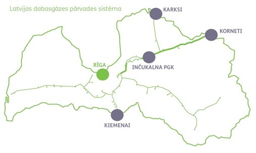
Physical flows of the natural gas transmission system of Latvia are provided from Lithuania (point of entry for Kiemenai) and from the withdrawal of natural gas from Inčukalns UGS during the winter season (point of entry for Inčukalns UGS).
In the transmission system, physical outflows are provided for Latvian consumers' supply (starting point for Latvian users' supply), Lithuania (starting point Kiemenai), Estonia (starting point Karsi) and Inčukalns UGS during the withdrawal season (starting point Inčukalns UGS).
The transmission system also provides input from storage during the suction season and exits to storage during the withdrawal season with virtual counterflows.
Description and history of gas transmission
The infrastructure of the Latvian natural gas transmission system shall be composed of:
- gas pipelines with closing fittings;
- gas control stations (GRS), gas adjustment units (GRM) and gas measuring station (GMS);
- telemechanisms, communications and electricity supply systems;
- electrochemical protection system;
- security systems.
General description of the Latvian natural gas transmission network
The transmission pipelines are composed of regional gas pipelines intended for Latvian supply, and international gas pipelines, which ensure gas transit to neighbouring countries, and their branches. The total length of the transmission pipelines together with the transmission pipeline branches is 1190 km.
The length of the international transmission pipelines is 577 km, consisting of the Riga – Pahneva, Pleskava - Riga, Izborska - Inčukalns UGS , Riga - Inčukalns UGS I - line, Riga - Inčukalns UGS II - line, Vireši - Tallinn pipelines.
The length of regional transmission pipelines is 613 km, consisting of Riga – Daugavpils, Iecava – Liepāja, Upmala – Preili – Rezekne gas pipelines and gas pipelines to gas control stations.
International gas pipelines have a diameter of DN700 with working pressure ranging from 28 to 50 bars, and regional gas pipelines have a diameter of BETWEEN DN100 and DN500 with working pressure up to 35 bar, with a design working pressure of up to 55 bar.
Table 1. Notional diameters characterising transmission system pipelines (mm)
| Notional diameters characterising transmission system pipelines in mm | Length km |
| pipeline diameters DN 700 | 577 |
| pipeline diameters DN 500 | 280 |
| pipeline diameters DN 400 | 20 |
| pipeline diameters DN 350 | 136 |
| pipeline diameters DN 300 | 47 |
| pipeline diameters DN 250 | 42 |
| pipeline diameters DN 200 | 31 |
| pipeline diameters DN 150 and less | 57 |
| Total: | 1190 |
Gas control stations and their operation
In order to transport natural gas from delivered to consumers, natural gas is compressed into compressor stations to maximum pressure and entered into gas transmission pipelines, so that work is carried out and the potential energy allocated to gas is allocated. Higher pressure value allows more natural gas to be transported and offset hydraulic losses. Since the pressure of the gas to be transported exceeds several times the pressure required for the final consumer, gas control stations (GRS) are installed before the distribution network.
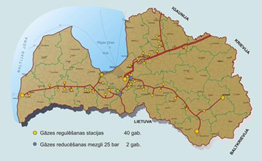
Figure 1. Geographical location of GRS and GRM
The GRS must ensure the supply of a specified quantity, pressure and temperature, purified and odorised natural gas by measuring its quantity to the natural gas distribution system.
GRS technological process
The system of principle for gas control stations is designed to ensure the continuous supply of natural gas to distribution networks. The model design involves two parallel lines: a work line and a spare line.
Such a two-line constructive solution provides an opportunity to direct the gas flow along one or the other line, depending on the technological need. In the event of damage to work-line equipment, a backup line automatically opens and gas flows around a damaged line, ensuring a continued supply of natural gas to consumers. Both the work and the spare line are equipped with the same equipment, but different with the gas safety closing valve, in the pressure setting.
Natural gas treatment
When natural gas flows into GRS, they initially come into special filters in separators, where the gas flow is separated from the liquid phase of the steam type and mechanical solid particles, thereby protecting meters and regulators from potential damage.
Recording of natural gas
The next technological phase after purification is the inventory of natural gas to be carried out in the various meters, the type of turbine and/or ultrasound. For more accurate metering, additional volume recorders are added to meters to make reading adjustments depending on gas temperature and pressure. In conformity with the requirements of regulatory enactments, meters shall be regularly locked in a series, thereby controlling the difference and operation of meter readings.
Natural gas heating
In order to avoid the formation and icing of glacial hydrates, which may result in reduced pressure, the natural gas is heated in special heat units.
Reduction of pressure on natural gas
As a result of the GRS technological process, the pressure on natural gas is reduced to the specified amount specified in the cooperation agreement with the distribution system operator. This ensures a smooth gas supply and pressure within the prescribed limits.
Odorization
Natural gas shall be in a clean state without any colour and odours which, in the event of leakage, makes it difficult to detect, so that it may pose a risk. Therefore, before natural gas enters the distribution operator, it is odorised, i.e. the odorant is added
Electrochemical protection
The objective of electrochemical protection is to minimise corrosion processes for pipes from transmission pipelines. The gas pipeline in Latvia is buried underground and is exposed to a variety of risk factors where metal corrosion can occur and be formed. The causes of corrosion may be:
- corroborating environment;
- class-current from electrified transport;
- alternating power lines from high voltage.
Each of these factors may cause significant damage to metal corrosion and, as a result, serious accidents. For corrosion protection of the gas pipeline, the following shall be used:
- protective coatings (passive protection);
- cathode protection (active protection);
- protection against claidstrings (active protection).
Corrosion protection measures shall be performed in accordance with the standards LVS 363: 2016 “Transmission (Transport) pipeline system. Additional requirements for the co-operation of steel underground gas pipelines” and LVS 423: 2016 “General requirements for the co-operation of steel underground gas pipelines”.
Protective coatings — Treatment of the external surface of the gas pipeline with a protective coating to protect the metal from various environmental factors.
Cathode protection - in places where the insulation coating has worn off, cathode stations provide protection for the pipeline. In this case, the rate of metal corrosion (decay) decreases due to the degree of oxidation reaction, the potential being moved more negatively than the potential for free corrosion.
Protection against claidstrings - In order to protect against claidstrings caused by electrified vehicles, drainage protection stations are used to divert the claids from the underground gas pipeline back into the electrified track chain.
In order to protect the gas pipeline from alternating power lines from high-voltage lines, protective blocks shall be used which direct the alternating current caused by the high-voltage power line from the gas pipeline to the sockets.
Dispatching
Management, control and monitoring of the operation of the natural gas transmission system and physical flows shall be ensured by controllers. Their role is to ensure continuous and safe transmission of gas within the natural gas transmission system through complex use of transmission and storage systems.
The duties of controllers shall include:
- To organise flows in the transmission system in accordance with requests submitted by natural gas transmission system users;
- Control the operation of the natural gas transmission system and its technological facilities;
- Follow the technical performance of natural gas flows and parameters in transmission pipelines and their facilities;
- Manage the gas supply of the region (Baltic States, Finland, Western Russian Federation) and provide flexible and secure natural gas supplies in cooperation with the transmission operators of the North-West regions of Lithuania, Estonia, Finland and Russia;
- Monitor the entry/exit points between the operator systems, coordinate the injection and withdrawal processes in the Inčukalns UGS ;
- Participate in the schedule of planned repair work;
- Ensure the operational exchange of information with technological structures on flowing regimes and operational issues and participate in emergency management;
Maintenance of the gas transmission system
The public shall ensure timely and continuous maintenance of the natural gas transmission infrastructure at a high level by performing such works as maintenance, inspection, repair, diagnostic and development work, in accordance with binding industry standards and regulatory enactments, such as LVS 364: 2020 “Natural gas storage facilities in aquifers and the operation, maintenance and repair of the transmission system” and technical maintenance rules for the Conexus natural gas storage system and the transmission system.
Modern and modern hardware and systems are used to maintain infrastructure. In addition, provision shall be made for rapid and operational action in emergency situations.
Priority attention shall be paid to the continuous functioning of the natural gas transmission system for the diagnosis and survey of gas pipelines and GRS (including gas reduction units and metering station) in order to detect and prevent defects or their potential occurrence in good time.
The detection or potential occurrence of defects is determined by different methods, which include measures to determine the condition of pipelines, technological installations, equipment, equipment, equipment and other equipment and engineering structures.
Determination and accounting of gas quality
In order to ensure proper settlement with suppliers of natural gas, gas records are required between carriers and consumers. It starts with the measurement of the volume flow, which takes place at natural gas measuring facilities. Depending on the main functions of the objects, gas control stations (GRS) and gas measuring stations (GMS) are distributed. Gas meters, temperature and pressure sensors are installed on these sites and gas quality points (GQS) may also be fitted to determine the qualitative gas parameters. Parameters such as gas temperature, pressure, gas composition, density and calorific value are necessary to convert the listed volume units into acceptable and comprehensible units under working conditions for all parties, as well as to calculate the amount of excess energy.
In gas transmission, the gas accounting function shall be part of one GMS and 40 GRS.
GMS Cornets upgraded and equipped with six ultrasound flow meters, two on each of the three measuring lines.
The most widely used GRS is turbine counters, but ultrasound meters are retrofitted and implemented sequentially.
The gas quality point shall normally contain a gas chromatography with the gases necessary for its operation. The gas chromatography shall determine the composition of the natural gas used for further calculations of the various qualitative parameters. This room also contains oxygen, humidity and other analysers. GMS Korneti GKP is equipped with two gas chromatography for high measurement safety and reliability.
History
The history of gas supply in Latvia developed in three technological stages:
- fuel gas use phase (1862-1962);
- phase of use of LPG (1949-to-date);
- natural gas use phase (1962-until now).
The beginning of Latvian gas supply is considered to be 1862, when the first gas factory was constructed in Riga to replace the lighting of the existing candles town lights to gas light. To this end, a system of 28.5 km of cast-iron gas pipelines was constructed through which the gas for the city lanterns was delivered. The average capacity planned for that time was 2 000 m3 and a maximum capacity of 5 700 m3 per day.
In 1882, Liepaja gas factory started to operate, reaching 26 km for the total length of the gas pipelines.
Around 1911 gas consumption amounts to 6.6 million m3 per year.
In 1939, the total length of the pipelines reached 132.2 km. Gas factory in Riga produces 8 million m3 gas gas gas gas, gas meters are set up to 13 thousand consumers and 1166 gas lamps are illuminated by cities.
In 1949, liquefied petroleum gas is imported from Western Ukraine. In Latvia, 10 residential areas were gazified at the time.
In 1962 Riga was reached by the main gas pipeline Dashava – Minsk – Viļna – Riga, for which natural gas was first flowing from Ukraine, and it was reached by Riga with a solemn ignition of a symbolic natural gas torch. The total length of the transmission pipeline Dashava - Riga was 1260 km.
In 1969, natural gas was also received in Liepaja.
In 1972, a new transmission pipeline linking Valdaja-Pleskavu-Riga is being built, based on an increase in demand for natural gas and an increasing number of cities with gas supplies.
At the end of the 1980 s, the total length of the pipelines reached 652 km.
By 2005, all current and commissioned gas pipelines were constructed.
The opening of the gas market in Latvia in 2017 resulting from the reorganisation of Latvian Gas, the joint natural gas transmission and storage operator “Conexus Baltic Grid” AS, which includes the gas transmission system.
In 2021, the first direct connection to the gas transmission system, aimed at ensuring the production of compressed natural gas, was put into service in the Priekuļi.